In 2D plan or profile mode, objects are drawn in the tab view in the order they are listed in the Plot Control tree. Objects are drawn in the tab view in the order in which they are listed in the Plot Control tree. Objects at the top of the list are drawn first. Thus, the objects at the bottom of the list will plot over items earlier on the list.
In 3D mode, objects are drawn from the perspective of a viewer, with objects closer to the viewer covering overlapping objects at greater distance. Some objects make sense only in the 3D viewing mode, such as 3D wells, 3D classed post, and 3D contour. Other objects are appropriately used in both 2D and 3D viewing modes, such as posted data, radial diagrams, and pie diagrams. For this latter group, the objects appear in the 2D viewing mode as flat 2D images. In the 3D viewing mode, they can be seen appropriately located vertically at the elevation of the measurement point. To work effectively in EnviroInsite, you must have an basic understanding of the render mode and how to control the 3D view.
Vertical Exaggeration
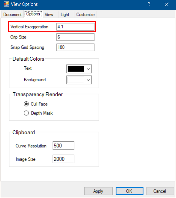
The vertical coordinates may be exaggerated in 3D displays. The magnitude of the vertical exaggeration relative to the horizontal scale can be specified by selecting View> Options from the main menu to open the View Option window. Select the Option tab and change the specified Vertical Exaggeration value.

Color Model
In the 3D view mode, an object is lit by both ambient and diffuse light, where ambient light is everywhere and directionless and diffuse light emanates from the direction of the user (outside the screen). The lighting of a particular surface is the sum of the two lighting effects. The default lighting intensities work pretty well in most circumstances, however, it may be useful to modify the light intensity obtain a particular effect. The light controls can be modified by selecting View> Options to open the View Option window and then selecting the Light tab.
View Modes
EnviroInsite will automatically select a view mode when the user:
•Switches between 2D and 3D views, or
•Draws 3D objects.
The viewing mode can be set with the View Mode option in the Tasks Pane. Five options are available: Wire, Hide Surfaces, Shade w/ Edges, Shade, and Render.
The Wire view mode is primarily for 2D plan and profile objects, where the display order is determined by the object order in the Plot Control tree.
The other four options are for 3D views, where the object draw order is determined by the distance from the viewer. Lines and surfaces that lie on the back side of surfaces (hidden lines and surfaces) are not visible. The 3D render modes differ principally in the way that surface colors and lines are displayed.
Hide Surfaces – Displays objects using 3D wire frame representation and hides lines representing back surfaces.
Shade with Edges – Surfaces are drawn in the selected color and lines are visible. This is the mode used most of the time in 3D plots.
Shade – Same as Render mode, but lines with no vertical thickness are not drawn.
Render – Same as Shade mode with correct representation of translucent and transparent objects. Render mode must be selected to see the soil images in stratigraphic models.
3D View
The viewing perspective can be set with the View From option in the Tasks Pane. Viewer perspective can be established from the Southwest, Southeast, Northeast or Northwest. If Top is selected, the view is zoomed to the image extent and switched to 2D wire mode, where the display order is determined by the object order in the Plot Control tree.
Three-dimensional objects can be rotated in the view window. Select the 3D Rotate ![]() icon from the toolbar to enable manual rotation of the view. Move the cursor into the window with the mouse. Press the left button and move the cursor with the mouse to rotate the view. Lifting the mouse button completes the rotation.
icon from the toolbar to enable manual rotation of the view. Move the cursor into the window with the mouse. Press the left button and move the cursor with the mouse to rotate the view. Lifting the mouse button completes the rotation.